The Game Port
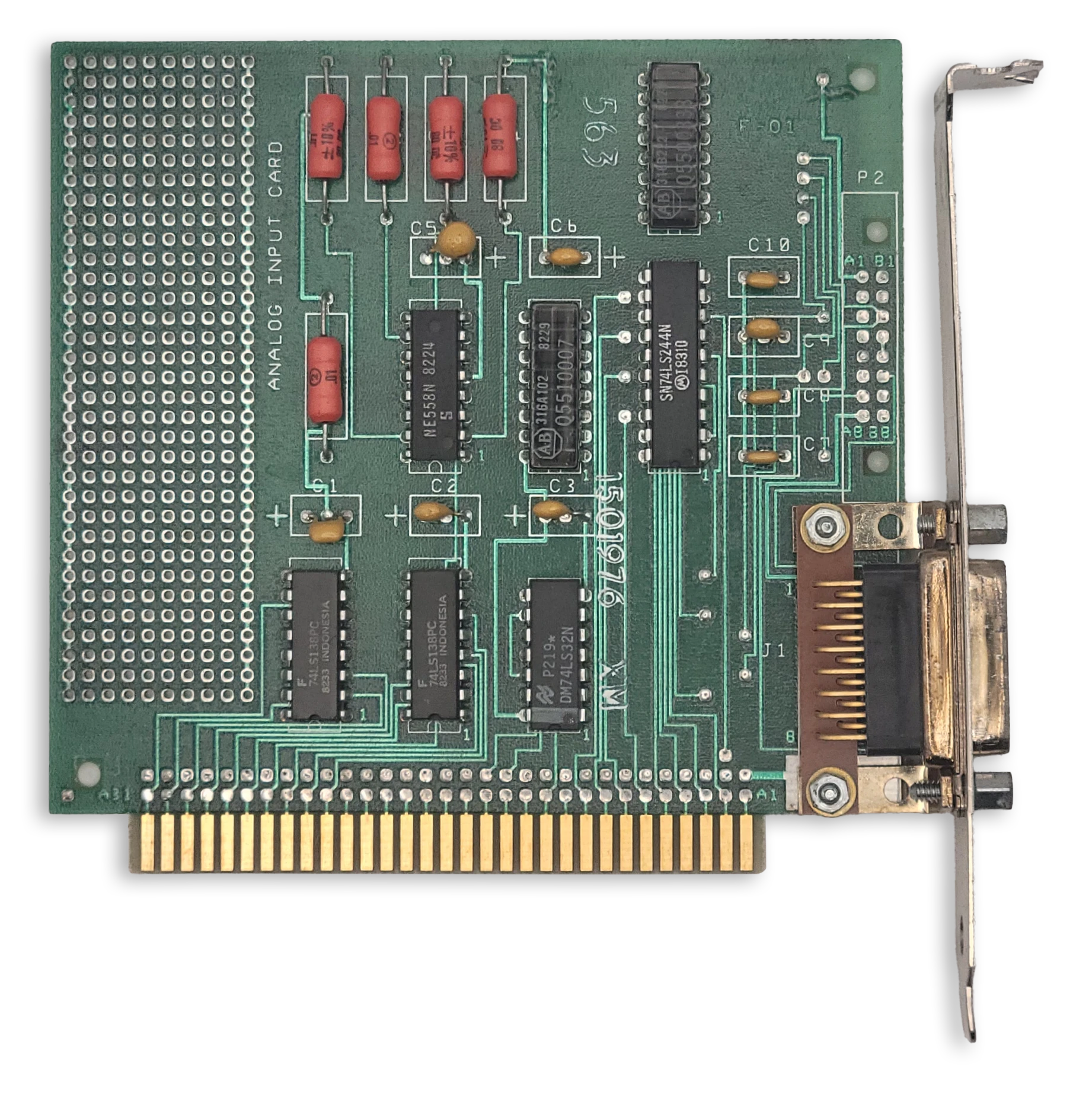
The IBM Game Control Adapter
The IBM Game Control Adapter implements a game port, supporting up to four buttons and four analog axes. In the early days of the PC, joysticks typically had two axes (one stick) and two buttons. Later on, gamepads with four buttons emerged, such as the Gravis PC Gamepad.
Eventually, joystick makers employed various schemes to support more than four buttons and inputs such as hat switches.
This included implementing bespoke digital protocols on top of the existing game port wiring. Digital joystick protocols will not be discussed here.
At a Glance
| Item | Description |
|---|---|
| I/O address | 201h |
| Interrupts | None |
| DMA | None |
Game Port Operation
The pinout of the game port itself presents a challenge: the position of each axis must somehow be read with a single wire.
To do so, each axis of a joystick is connected to a potentiometer. A capacitor on the game port card and the potentiometer within the joystick form an RC timing network connected to one of four monostable timers on an NE558N quad-timer chip. This creates a one-shot timing pulse of a duration given by the following formula:
$$ T(\mu\mathrm{s}) = 24.2\mu\mathrm{s} + 0.011r\ \mu\mathrm{s} $$
To read the axis positions, first port 201h must be written to in order to trigger the four timers. This will cause bits 0-3 of 201h to read high. Port 201h must then be polled repeatedly until one axis bit changes from 1 to 0. At this point, the elapsed time T (in microseconds) can provide the resistance value for that axis:
$$ r(\Omega) = \frac{T(\mu\mathrm{s}) - 24.2}{0.011} $$
The measured resistance value can be normalized to the range [0.0-1.0] by dividing by the maximum resistance. The potentiometers in the joystick typically have a range of 0 to 100kΩ. An emulator can simulate an ideal joystick with a perfect, linear response within this full range. Real joysticks were imperfect, and so many applications that used a joystick had a calibration routine where the user was asked to move the stick to the maximum extent of each axis before pressing a button. In this way the effective range of the potentiometer could be determined.
When the stick of a joystick is auto-centered, the stick is said to be in its neutral position. In the neutral position, the joystick may not read at the exact center of its range. Some joysticks included trim controls that could be used to adjust the center position until it read correctly. A robust joystick calibration routine should also capture the neutral position to account for any off-center readings.
Without sufficient calibration, a phenomenon known as drift may occur where an unintended directional input is produced while the joystick remains in the neutral position.
One way for a programmer to address drift was to establish a dead zone, a square region or radius within which any calculated stick position is snapped to the ideal neutral position.
Reading Buttons
The immediate state of the four buttons can be read out at any time, as active-low inputs.
The Game Port Status Register
| Bits | Name | Description |
|---|---|---|
| 0 | A-X | Joystick A X-coordinate one-shot output. 0: Timing pulse ended 1: One-shot fired / timing pulse active |
| 1 | A-Y | Joystick A Y-coordinate one-shot output. 0: Timing pulse ended 1: One-shot fired / timing pulse active |
| 2 | B-X | Joystick B X-coordinate one-shot output. 0: Timing pulse ended 1: One-shot fired / timing pulse active |
| 3 | B-Y | Joystick B Y-coordinate one-shot output. 0: Timing pulse ended 1: One-shot fired / timing pulse active |
| 4 | A1 | Joystick A button 1. 0: Pressed 1: Open / not pressed |
| 5 | A2 | Joystick A button 2. 0: Pressed 1: Open / not pressed |
| 6 | B1 | Joystick B button 1. 0: Pressed 1: Open / not pressed |
| 7 | B2 | Joystick B button 2. 0: Pressed 1: Open / not pressed |
Typical Joystick
A typical joystick of the original PC era would have a single stick, and one or two buttons. The IBM PCjr joystick pictured below was a rebadged Kraft joystick that could also be purchased for a standard PC game port. This joystick, like many others, can be converted per-axis from auto-centering to free movement, something probably only useful for flight-simulator games.
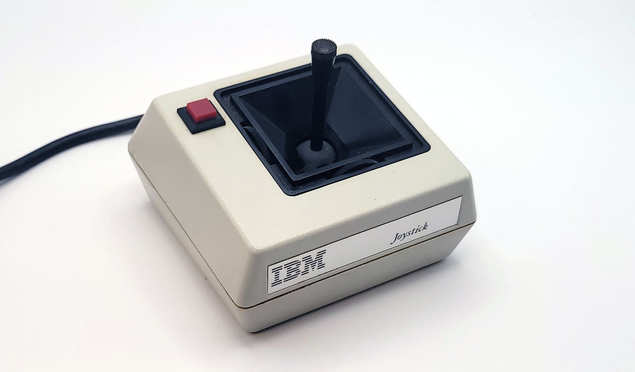
The IBM Joystick
Typical Game Pad
Game pads typically had a directional pad (or D-pad) that acted in a digital fashion, snapping to the farthest extent of either of two joystick axes when a direction was pressed. Directional pads were more suitable for fast action games and were the primary means of directional input for popular home video game consoles such as the NES.
The Gravis PC GamePad shown here could be switched between left and right-hand operation, as well as between two and four-button mode. Two gamepads could only be used at the same time in two-button mode.
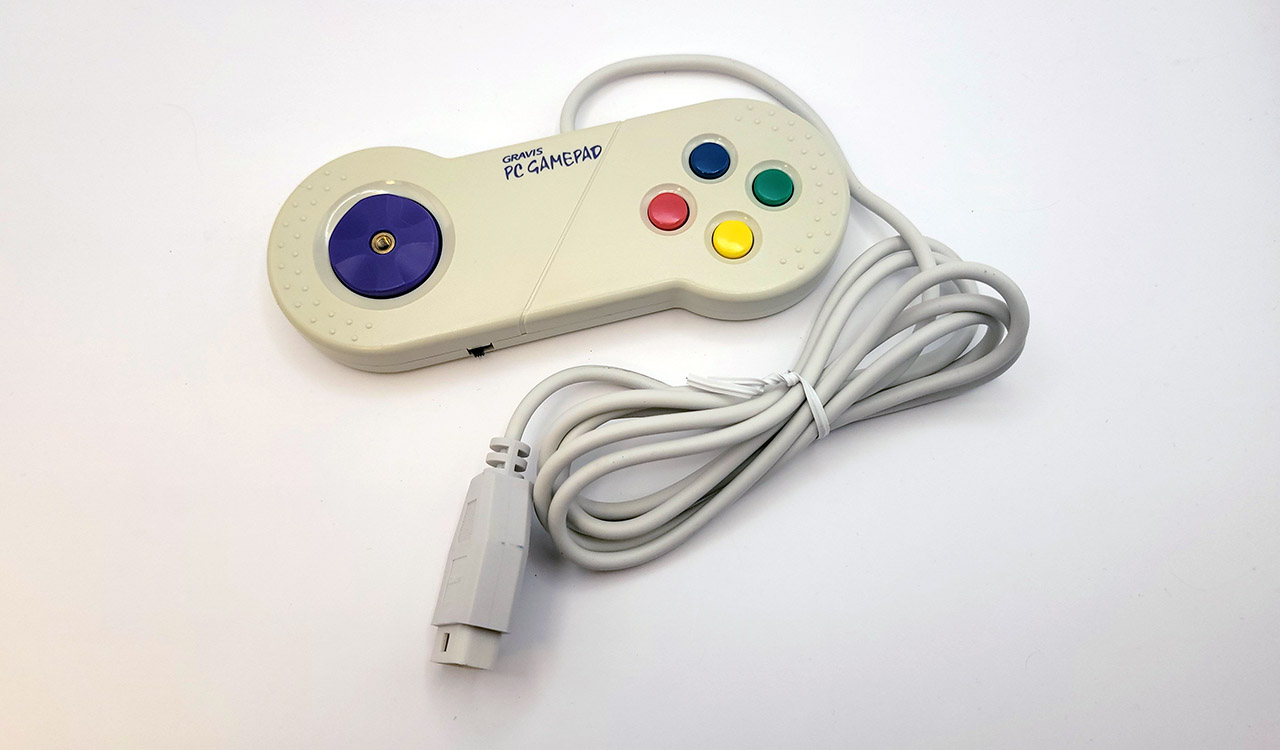
The Gravis PC Gamepad
Hat Switches
A hat switch is a multidirectional input present on some joysticks that is typically operated with the user’s thumb. It typically allows four directions of input, and can be useful in flight simulators for changing camera views or navigating through menus.
Two separate and incompatible techniques emerged for encoding hat switch input.
Thrustmaster Hat Switch Input
The first came from the joystick manufacturer Thrustmaster to support the hat switch on the Thrustmaster FCS.
The four positions of the hat switch were encoded as five specific resistance values measured on the single B-Y axis.
| Value | Hat position |
|---|---|
| 0.2 kΩ | Up |
| 20 kΩ | Right |
| 40 kΩ | Down |
| 60 kΩ | Left |
| 82 kΩ | Center |
This implies interpreting resistance bands as follows:
| Low | High | Center Fraction | Hat position |
|---|---|---|---|
| 0 kΩ | 10 kΩ | 1/8 | Up |
| 10 kΩ | 31 kΩ | 3/8 | Right |
| 31 kΩ | 51 kΩ | 5/8 | Down |
| 51 kΩ | 72 kΩ | 7/8 | Left |
| 72 kΩ | ~ | Center |
Note
Various references conflict on the ordering of these inputs. This is the ordering used by the Linux analog joystick driver, and several modern microcontroller projects.
CH Products Hat Switch Input
The competing hat switch encoding standard was from CH Products. In this scheme, multiple inputs or chords of the standard four buttons encode the hat switch position. The downside of this scheme is losing the ability to register more than one simultaneous button press during normal input.
| Button A1 | Button A2 | Button B1 | Button B2 | Hat position |
|---|---|---|---|---|
| 0 | 0 | 1 | 0 | Right |
| 0 | 0 | 1 | 1 | Left |
| 0 | 0 | 0 | 0 | Up |
| 0 | 0 | 0 | 1 | Down |
If multiple buttons are pressed, only a single button will register, based on the lowest priority number.
| Button | Priority |
|---|---|
| A1 | 1 |
| A2 | 2 |
| B1 | 3 |
| B2 | 4 |
Radial Remapping
Modern analog sticks are typically circular, producing coordinate pairs in the unit circle:
$$ x^2 + y^2 \leq 1 $$
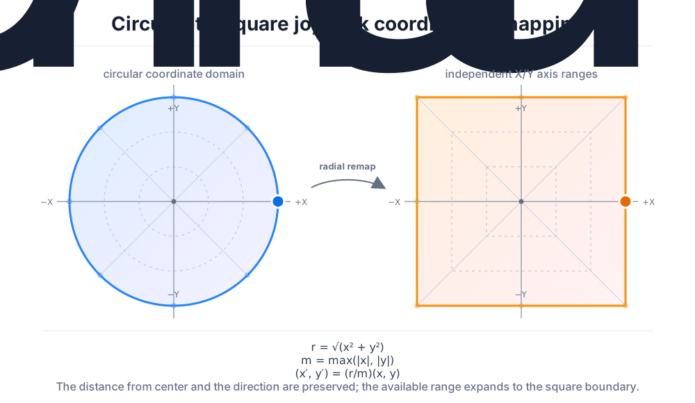
Traditional joysticks typically allowed the full range of each axis independently. This can cause problems when calibrating a joystick via diagonal inputs with a modern gamepad. It may be useful to translate radial coordinates to square ones:
$$ r = \sqrt{x^2 + y^2}, \qquad m = \max\left(|x|, |y|\right), \qquad (x’, y’) = \frac{r}{m}(x, y) $$
This produces the following remapping:
Game Port Evolution
The game port didn’t exist for long as a standalone card, although several companies produced their own versions, sometimes with a trim adjustment knob for better calibration. Game ports instead started to appear on many multifunction cards like the AST SixPakPlus. Eventually, the game port would migrate almost entirely to PC sound cards such as the SoundBlaster, where the port also served a secondary role as a MIDI port.
Utilities
- (www.oldskool.org) JOYCALIB is an excellent joystick calibration utility made by Trixter. It can be very useful for testing your game port and joystick emulation.
Datasheet
- (archive.org) The IBM Game Control Adapter
Primary References
- (atrey.karlin.mff.cuni.cz @ archive.org) Vojtech Pavlik’s Joytic Specifications
- (epanorma.net) Joysticks and other game controllers
- (davenunez.wordpress.com @ archive.org) Reading hat switches on PC gameport joysticks
- (nerdlypleasures.blogspot.com) Three Flight Simulator Joysticks for DOS
- (github.com) /drivers/input/joystick/analog.c